In elementary school, we learned to add with carries. Binary addition works the same way, with the following algorithm:
- Add LSBs and overflow from previous add.
- Carry the overflow to the next addition.
- Shift two addends and sum one bit to the right.
Now, we’ll build this in hardware. The primary concern is to make this as fast as possible—addition is used everywhere.
Half Adder
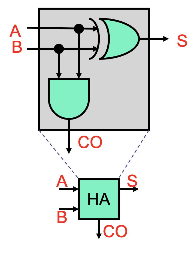
The half adder adds two bits A and B. There are only four possible input combinations, and we find that the sum S and carry-out CO are:
S = A ^ B(where^is XOR).CO = AB(implied AND).
Full Adder
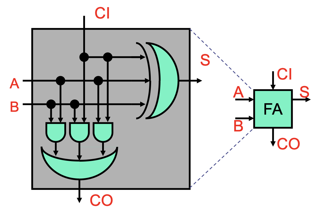
To add bigger numbers, we need to incorporate the carry C from the previous bit. Thus, we’re actually adding three bits in the full adder:
S = C'A'B | C'AB' | C'B' | CAB = C ^ A ^ B(where'is NOT,|is OR).CO = C'AB | CA'B | CAB' | CAB = CA | CB | AB.
Ripple-Carry Adder
Now, to add bigger numbers, we can chain the full adders together, giving us the ripple-carry adder. A
making it linear in the number of bits and way too slow.
Carry-Select Adder
To speed things up, we note a common pattern in hardware: we can trade resources for latency. One example is speculation: if our computation is slow because some components are waiting for input, we can compute with all possible inputs beforehand and choose the right one later. This is the idea behind the carry-select adder.
Our ripple-carry adder is slow because each full adder is waiting for the carry from the one before it. To speed things up, we can divide the ripple-carry adder into halves:
- The first half (bits
to ) will compute as normal. - The second half (bits
to ) will be duplicated; one copy computes assuming the incoming carry is , and one copy assumes it’s . Afterwards, based on the result from the first half, we’ll choose the correct copy’s output using a mux.
A multi-segment carry-select adder extends this idea, breaking the chain into multiple segments and optimizing for the delay.
- A two-segment carry-select adder’s delay is
(with coming from the selection mux). - A
-segment carry-select adder’s delay is
Carry-Lookahead Adder
We can go even faster than the carry-select. The bottleneck is the carries, so we can use even more hardware to compute them quickly.
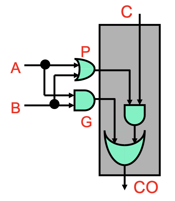
First, we’ll reframe the single-bit (full) carry function: CO = AB|AC|BC = (AB)|(A|B)C. This is an OR between two components:
AB, which we call generateG, will cause a carry-out regardless of the incomingC.A|B, which we call propagateP, will cause a carry-out only ifCis 1—effectively propagating the incomingC.
Now, we have CO = G|PC.

Unrolling this recursive function, we can see that our carries can actually be expressed as a bunch of ANDs and ORs with constant depth. This requires a lot of large gates that isn’t feasible in hardware, but it’s a strong upper bound—constant gate delay to compute carries, which allows us to have constant gate delay for addition.
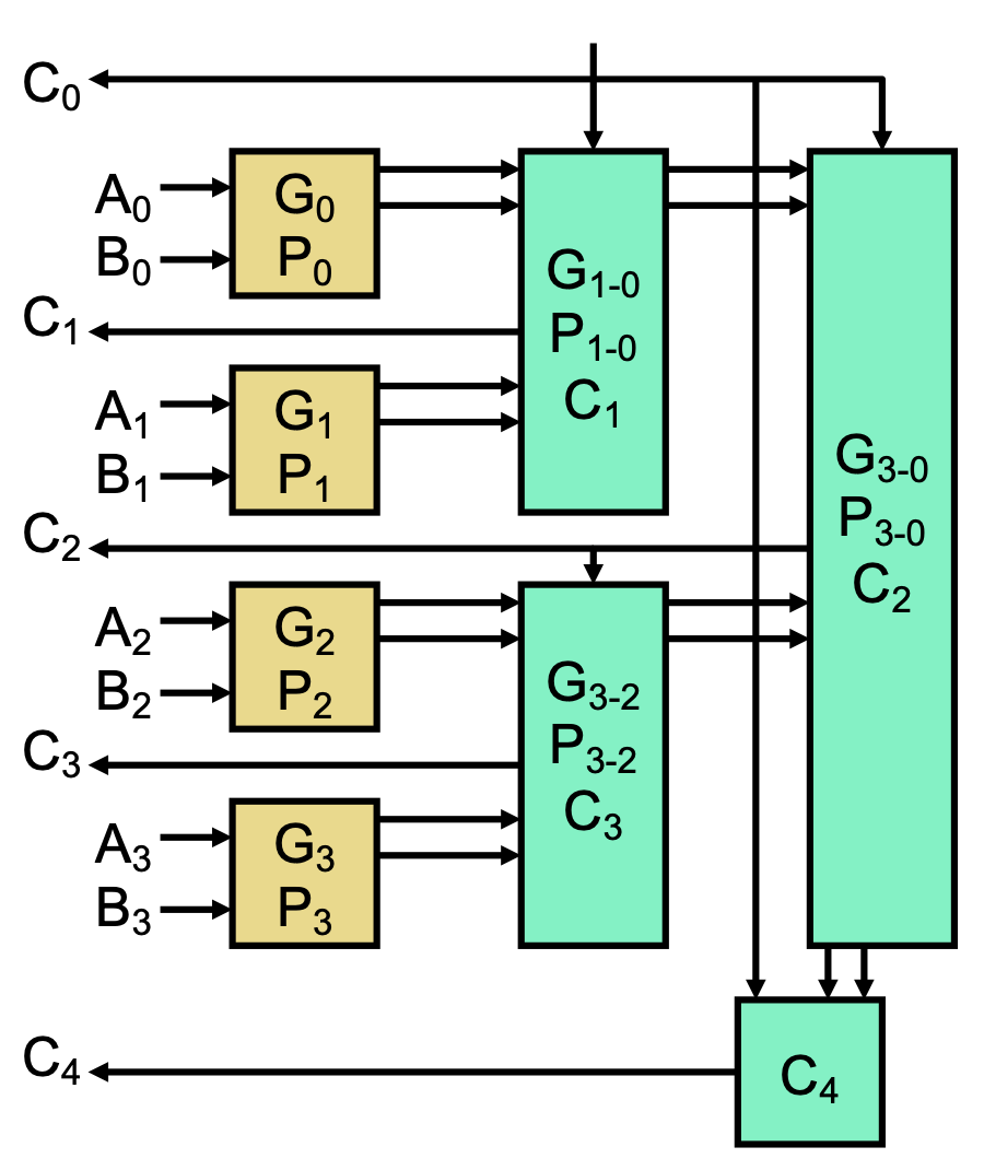
In reality, we can achieve a compromise with a reasonable number of small gates in the carry-lookahead adder (CLA). We first compute P and G based on A and B, then use a tree-like structure to compute the carries, resulting in logarithmic delay.
In this multi-level CLA, we can simply the carry equations with “chunks” of G and P, called windows.
G[i, 0] = G[i] | P[i] G[i-1] | …summarizes the generate bits fromito0. That is, will the generate bits inside this window propagate toi?P[i, 0] = P[i] P[i-1] …summarizes the propagate bits fromito0. That is, will a carry-in to0create a carry-out ati?
We can imagine the tree-like structure as computing these windows in parallel on each level, with small windows on the bottom and bigger windows near the top. For example, with
- First level: compute
G[1, 0], P[1, 0], G[3, 2], P[3, 2]. - Second-level: compute
G[3, 0], P[3, 0]. We can then calculate:
 C[1] = G[0] | P[0] C[0]with 3 gate delays.C[2] = G[1, 0] | P[1, 0] C[0]with 5 gate delays.C[3] = G[2] | P[2] C[2]with 7 gate delays.C[4] = G[3, 0] | P[3, 0] C[0]with 7 gate delays.
Afterwards, we can compute the actual sum with one more delay.
Note that the 4-bit CLA isn’t actually better than the ripple-carry adder, but as we scale this up, its latency becomes much more advantageous.