The datapath implements the hardware necessary for manipulating the computer state based on an instruction. Within it, we have:
- Register file: a collection of registers with an interface with reading and writing to registers via "ports." Also receives write-enable signal.
- ALUs: performs arithmetic operations on inputs.
- Data memory: stores state with an interface for reading and writing to addresses.
- Muxes: chooses which wire signal to send as output based on the selector wire. The selector wire is set by the control unit.
Stateful Components
Register File
The register file consists of a decoder, which converts a binary integer to 1-hot (with zero-indexed input
Data Memory
Memory is similar to the register file, but it has much more storage (more words) and few ports, which are shared for read and write. It receives a target address, write-enable, and input data, and it outputs the address data.
Pipelining
The most basic datapath setup is a single-cycle datapath—one instruction completes per clock cycle. This means that the clock frequency must be set to accommodate the critical path—max-delay path between two registers.
Pipelined Divider
One of the slowest parts of our datapath is the divider. To improve performance, we can add a register in between the divider; we can start a new division operation each cycle, but it will only complete halfway, and the other half will be done in the next cycle. This boosts throughput since we can now parallelize divisions (one half does one division, the other half starts a new division) at the cost of latency due to the extra register. Note that if the next division depends on the previous one, we skip a cycle to wait for the division to finish.
Pipelined Datapath
We can apply this principle to the entire datapath by breaking instruction execution into stages; each stage will be executing an instruction—like a stage-level parallelism—allowing us to significantly increase throughput even though individual instructions aren't actually faster. With this method, the clock period is the maximum delay of the stages rather than the total delay of all stages, though the CPI (from ⚡️ Performance) is higher than 1 since the pipeline often stalls for dependencies.
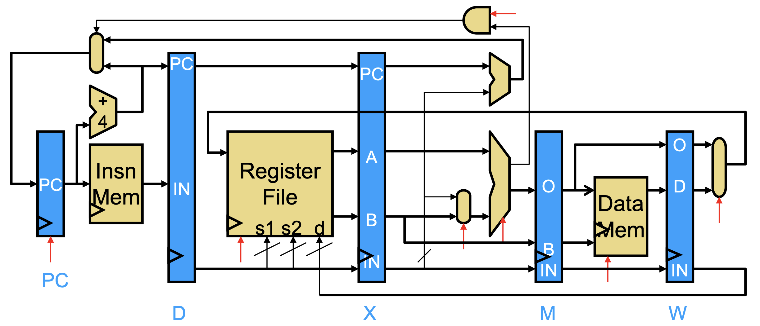
Specifically, we can use a 5-stage pipeline: Fetch, Decode, eXecute, Memory, Writeback. The registers between the stages are named F, D, X, M, W. In this setup, the pipeline is scalar (one instruction per stage per cycle) and in-order (instructions enter execute stage in program order).
- Fetch gets the instruction from instruction memory using the PC.
- Decode decodes the instruction bits into signals.
- Execute performs the necessary computations for the instruction.
- Memory accesses data memory (for loads and stores).
- Writeback writes results back to the register file.
Dependencies and Hazards
When executing instructions, it's possible that there's a dependency between two instructions—whether it's data (using same state) or control (one instruction affects whether the other runs). While this isn't a concern in the single-cycle datapath, it causes potential hazards in a pipelined datapath, where a dependence introduces the possibility of a wrong instruction execution.
Data hazards occur when an instruction accesses a state before it's ready (before a previous instruction is done). To this, the processor can compare the input register names from the instruction in the D-stage to previous instructions, and if they match, it prevents the D-stage instruction from advancing by inserting a hardware NOP (no-op, also called stall or bubble). This can be slow, however, and we can make it faster with 🏎️ Bypassing.
Control hazards happen when the processor fetches instructions that shouldn't have run. This is possible due to speculative execution: instead of waiting for the branch result, we "guess" which branch to take and run before we know whether it's correct or not—this is called 🕊️ Branch Prediction. If the prediction is correct, we gain a speed boost; otherwise, we flush the incorrect instructions.
We can tell misprediction during execute, so we know that instructions in fetch and decode are wrong. Since they haven't written permanent state (registers or memory), we can replace them with NOPs and incur a 2-cycle penalty. We can optimize this a bit further by testing branch comparisons with zero or equality in the decode stage (without using ALU in execute) for a 1-cycle penalty.
An alternative to branch prediction is ⚔️ Predication.
Multi-Cycle Operations
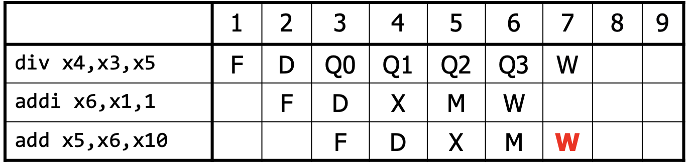
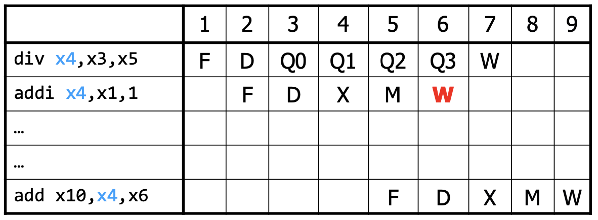
Some operations, like division, are much more expensive than others. Thus, it might make sense to make this operation itself a multi-cycle calculation (as described above). In this case, some instructions will take more cycles to complete than others, which might cause a structural hazard: two instructions try to use the same circuit at the same time.
To prevent the structural hazard, we need to stall the subsequent instruction. Moreover, we also need to update the data hazard stalls to wait until the multi-cycle operation completes. Lastly, we need to stall mis-ordered writes, which can occur when the next instruction after a multi-cycle operation instruction finishes earlier.
Pipeline Depth
As we increase the number of pipeline stages, we can increase clock frequency at the cost of CPI, more hazards, and higher memory latency. Note that even with more stages, register overhead and imbalanced stages means that the frequency increase won't be proportional. After some point, deeper pipelining can decrease performance.